


First, a few notes and ramblings before I get into the how-to (READ FIRST):
- Limit bus distance from the power unit. If you don’t you’ll have voltage drops and, much more importantly, you won’t reliably detect shorts. There’s are ways to test for this such as using a RRAmpMeter or shorting the two rails with a quarter however the point is your bus length, right from the output of the command station/booster, all the way to the end of the bus should never exceed 40 feet.
- (Expanding on above) design/place your power unit for shortest bus cables. What I mean by this is don’t build a “rolling toolbox” type of setup, and place it 20 feet away under the crew table or at one end of the layout because it’s convenient. I recommend you place your unit in the center of the layout, running two buses and thus cutting down distance for each bus (anything larger than two bus runs probably needs an additional booster module or more). I also believe in table-top or module-based power units that go right into the layout, eliminating all header/pigtail cables.
- Run dedicated circuit protection. The one built in to your command station/booster does not count. I have seen a command station happily melt trucks on a passenger car without correctly detecting it as a short. I currently recommend the DCC Specialities PSX line of units, but most DCC systems also offer a comparable unit, such as Digitraxs’ PM42. Each bus exit from the power unit needs a circuit breaker for yellow and for red (I run four total for two bus exits).
- Provide accessory power. I believe in this day and age of shrinking attention spans, it’s important to promote the use of sound, lighting and motion. The way to do this is to offer accessory power via the same bus rather than running a mess of AC cords, strips and wall adapters. I highly recommend that 12-13VDC is provided. It’s a very common voltage, and anyone that needs other voltage such as 5VDC can wire in their own DC-DC adjustment device that’s either purpose built or can be intended for car/boat use. It also makes providing the power easier, since it’s the same type of power the booster/controller would already be using. Speaking of, make sure you run a fuse for each bus exit, preferably resettable, in case there’s a short.
Materials you’ll need
- Bus cable. For these instructions you need three pairs of 14AWG stranded copper wire cut to ten foot lengths. It can be speaker cable, zipper cable, or my favorite source, extension cord. I buy contractor-grade (yellow jacket) extension cord and de-sheath it. It’s guaranteed to hold up to coiling/flexing/throwing/etc. and is easy to acquire cheaply (my last purchase worked out to 70 cents a foot for three pair), and for two extension cord lengths you end up with two black/white pairs, and two green wires to use for the accessory wires.
- Accessory feeder wire. I use wire from old orange extension cords, but anything will do.
- Module feeder connections. T-trak standard specifies Kato connectors. I recommend using Kato 3-way splitters in pairs, one for yellow and one for red. You should figure on powering every three feet of module on each side of the bus, which means you need six (three pairs) of the 3-way adapters per ten feet. You’ll eventually want to have some of Kato’s extension cables for hard to reach modules too, FYI.

- Bus, power unit and accessory connections. Anderson Powerpole. 30-amp crimps for the bus, (possibly) 15-amp crimps for accessory feeders, white, red, yellow, & (3x as many) black crimp housings, six-connector powerpak inline connectors (with and without clips) & roll pins for bus-ends, six-connector outlets/roll pins for the power unit. If I get more time I’ll add part numbers. My favorite source for these parts is Allied Electronics, in Texas. They deal in any quantity, have lots of stock, and shipping is fast and very reasonable. Over estimate what you need and build a parts kit.

- Bus protection. Split wire loom. The loom size will vary based on your wire used, but you need one size for the bus run itself, and a smaller size for covering feeder and accessory wires that come off the bus.
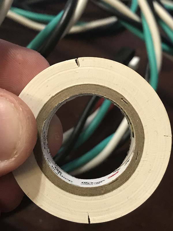
- Red/Yellow/Accessory markings. You’ll need to show which of your feeders goes to what, as well as, in some cases, marking the bus cable itself inside its’ loom. You could swipe it with paint or wrap with any kind of durable sticker… I recommend a smaller multicolor pack of electrical tape, and score the rolls which allows for easy small colored strips when you need them.
- Electrical tape. You’ll need lots of it. Get the good stuff! 3M, Super 88.
Tools you’ll need
- Self-adjusting wire stripper (specifically the kind where the wire lays across it, facing you)
- Dykes, flush cutters or hobby knife to split apart wire pairs
- Box cutter (fresh blade) or hobby knife to de-sheath extension cord
- Powerpole crimping tool
- Small awl or other sharp pointy tool, think ice pick
- (Optional) a cable cutter is convenient for chopping cable into length, especially with extension cords.

OK, ready to go? Here’s the step by step!
Cut/prepare bus cables
Chop your bus cable into 10-foot sections. If you’re doing extension cords, de-sheath it (take the jacket off of it). Your goal is to end up with three pairs of wires in ten foot sections. If you need to, label the wires red/yellow/white in some way. With extension cords, I label one black/white as red, the other as yellow, and one of the two ground cables gets a white mark… every few feet is OK, it just makes your job easier when adding feeders.


Strip, crimp, and finish the ends
- Strip off the ends of the bus wires and twist if needed. Look at a Powerpole crimp to judge the strip length.
- Install 30 amp Powerpole crimps with the tool. Don’t crimp too far onto the tongue or you’ll have trouble with the housing in the next step. Give it a firm tug afterwards to make sure it’s on good. The tool has an adjustable stop if you’re not crimping hard enough.
- Slide on the appropriately colored housings and make sure the tongue is engaged (you shouldn’t be able to pull it back off). The pointy tool is handy if you need to remove a housing by separating the crimp tongue from the housing’s metal retainer tab.
- Thread connectors one at a time through a Power pak inline housing… one end of the bus gets a power pak housing with a clip, the other end is without a clip.
- Lock the connector housings into each other via the tongue and grooves on the sides of the housings. Double check the positions/orientations of the connectors, then slide the Power pak inline housing over them.
- The Powerpak inline housing has three positions the rolled pins can go into. The end with the clip needs to have the connectors all the way exposed, and the other end fully recessed.
- Install roll pin into Powerpak inline housing by starting the pin, then pushing the pin in by pushing the housing, pin down, onto a hard surface while wiggling the wires to making sure the hole in the assembly stays aligned. The pin shouldn’t stick out either side when done.
- When you’re finished, the two bus ends should be able to “click” together with colors matching.


Preparing and adding kato 3-ways
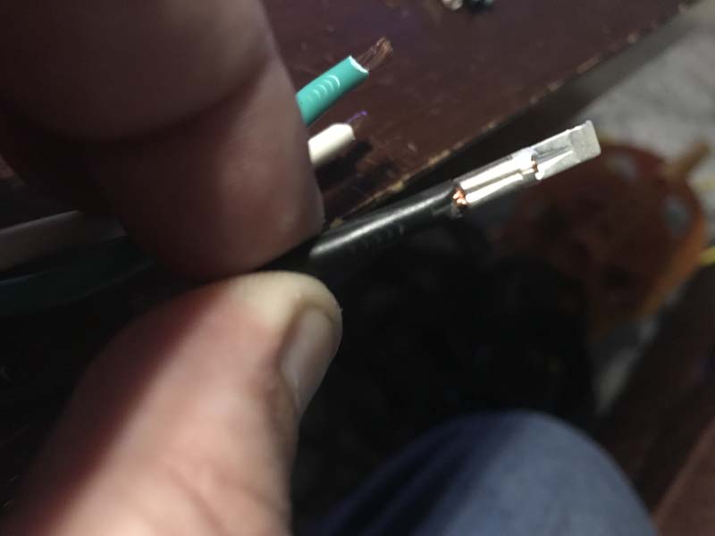
- Chop off the Kato connector and strip and twist the 3-way wire ends, the ends need to be a longer strip (see pic). Twist together the blues and whites on two red 3-ways, and same on the yellow pair.
- mark the 3-ways with red and yellow. The small electrical tape is great here.
- Pick where the 3-ways will be installed, if you’re installing three pairs, put one pair in center of the cable, and the others half way towards the ends.
- Split the wire using the self-adjusting wire stripper to pull the jacket away from the wire itself (see pic).
- Use your sharp pointy tool to create a hole in the middle of the wire strands, and put the feeder wire through and wrap it around the bus wire, going on both sides of the hole. Test it by giving it a tug.
- Wrap the splice with electrical tape (see pic).


Preparing and adding 12VDC
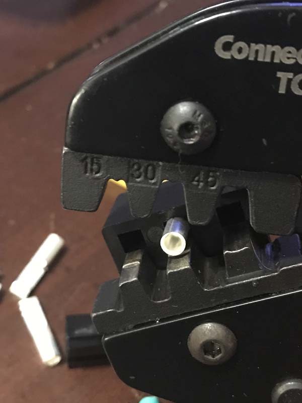
Do the same routine as above, but you’ll need a smaller gauge wire about 30” long; I use orange extension cord fragments. One end will need white/black Powerpole connectors and 30-amp or 13-amp crimps (see pic), the other end is secured in the same manner as the 3-ways above in a T splice onto the accessory wires.


Adding wire loom
Install both sizes of split loom then wrap all ends and junctions with electrical tape, as well as periodic wraps of taps to prevent the wire from poking out along the length.
The power unit
I like the outlet housings because they can be flush and there are no hanging wires or pigtails during transport. Use six-connector outlets and roll pins to install the connectors in the recessed position on the power unit. Use the steps for the bus cable, the outlet secures around the connector assembly just like the power pak housing but is designed to snap into a cutout afterwards. The bus cable end with the clip and exposed connectors should match and click into place to give you a secure connection.
All done!
(ignore the ends pictured, I changed these to the six-connector later)
